 Source: Aviation Week – aviationweek.com
By Guy Norris
Aviation Week tours hybrid airship as preparations for return to flight step into high gear.
A century after work began on the first of Cardington’s giant hangars, or “sheds,” as part of efforts to help Britain counter German airship dominance during World War I, a new-generation lighter-than-air vehicle is being prepared for flight testing inside the cavernous structure.
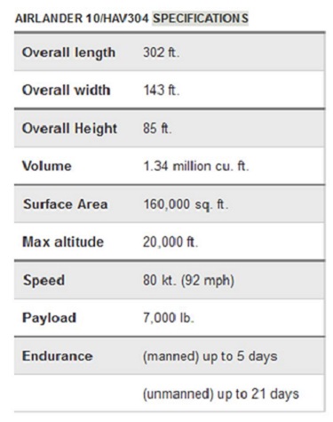
Occupying the entire eastern half of the 812-ft.-long No. 1 shed, U.K. airship developer Hybrid Air Vehicles (HAV) has officially launched the “return-to-flight” program for its Airlander 10 vehicle and expects to begin flight tests early in 2016. The Bedfordshire-based company is rebuilding the 302-ft.-long HAV304/Airlander 10 after acquiring it from the U.S. Army following cancelation of the Northrop Grumman-led Long-Endurance Multi-intelligence Vehicle (LEMV) program and sees a bright future for the technology in both government and commercial service.
The vehicle, which flew once as the LEMV in 2012, was transferred to the U.K. the following year and is being modified into the Airlander 10 prototype. Designed to demonstrate the multirole capabilities of the existing vehicle for everything from persistent surveillance to disaster relief, the hybrid vehicle will also pave the way for a planned larger variant called the Airlander 50.
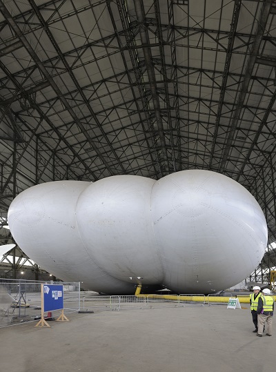
Airship Envelope and Structure
A yellow air duct keeps the Airlander 10 inflated for now, though helium will be pumped in later this year. The aft end, visible in this view, will house propulsors and tail units on the end of the outer lobes.
Credit: Mark Wagner, Aviation-Images.comThe Airlander is a hybrid airship because it uses both aerostatic and aerodynamic lift. Around 60% of its lift is created by the buoyancy of lighter-than-air helium gas. The balance is generated by forward movement of the aerodynamically shaped vehicle as it is propelled by thrust from its four propulsors. The airship weighs just over 1 ton on the ground, helping with controllability, says HAV. The helium is retained within an envelope made up of 5 tons of multilayered Vectran weave, Tedlar, Mylar and polyurethane. Pound for pound, Vectran is claimed to be 10 times stronger than aluminum and consists of a high-performance multifilament yarn spun from liquid crystal polymer. Tedlar, which is also used on the Goodyear blimp fleet, protects the entire envelope from weathering and is made from a polyvinyl fluoride film. The Mylar layer forms a gas barrier and is sandwiched centrally between layers by polyurethane film.
The vehicle is a pressure-stabilized structure and “gets all its strength from being inflated to just above atmospheric pressure with a 4-in. water gauge pressure differential (about 0.15 psi),” says HAV Technical Director Mike Durham. Despite the relatively small amount of pressure, the strength is derived from the airship’s huge diameter. “It acts as a pressure vessel and creates a skin tension in the hull because of the internal pressure.” Skin tension is a function of pressure multiplied by radius. “We have little pressure but lots of radius. I can walk along the top of the hull and I sink in just 0.5 in., so it’s a very stiff structure,” Durham adds.
Without an internal structural framework, how can the pressure vessel support tons of equipment and payloads of up to 7,000 lb.? “The payload module has pickup points on every single frame,” explains Durham. “We have a cable that runs up and punches into the interior of the hull, which is a figure-8 shape with a septum diaphragm in the middle. The payload sits in a cleft underneath. The cables come up on either side of the diaphragm to which large patches are bonded. All the loads are fed into that 300-ft.-long central diaphragm from where they are distributed out along the top surface,” he adds.
The hull is segregated into six main compartments with additional sub-divisions. “We have the ability to close segments of the hull in case of emergencies,” says Durham. “So if, for example, you took missile damage in one corner of the vehicle, we can protect the helium/lift carrying capability of the remaining three-quarters of the vehicle.” The compartment walls incorporate 30-in.-dia. holes which, in the event of a major leak in one area, can be plugged with an inflatable sausage-shaped balloon. “That’s the prime reason for the diaphragms,” he adds.
The compartments fore and aft and either side also house ballonets, or airbags, that are used for pressure control of the vehicle. The ballonets are inflated with air on the ground, reducing the volume available for the lifting gas, making it denser. Because air is also denser than the lifting gas, inflating the ballonet reduces the overall lift while deflating it increases lift. In this way, the ballonet helps to adjust the lift as required. There is also a septum diaphragm in the ballonet compartment to prevent mixing of the helium in the upper section and air in the lower part.
“As you go up in altitude, the air wants to expand and you can’t cope with trying to contain it with the strength of the hull, so the helium pushes down on the ballonets and pushes air out through valves,” says Durham. “When you come back down the helium wants to contract, so the ship would go soggy unless you push air back into the ballonets. So each ballonet has a big valve and fan in it so can vent air in and out and run the ship at a constant delta p. It’s the one system on the vehicle that’s got no parallel to any other aircraft or helicopter,” he adds.
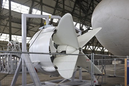
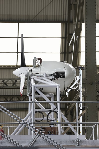
Propulsion and Thrust Vectoring
Thrust-vectoring vanes are mounted on the propulsor duct.
Credit: Mark Wagner, Aviation-Images.comOne of the Airlander’s four 350-hp. diesel engines is undergoing performance calibration tests with and without the enclosing duct.
Credit: Mark Wagner, Aviation-Images.comThe Airlander 10 is powered by four Continental (Thielert-developed) 350-hp diesels driving three-bladed, ducted props. The entire assembly of the two side-mounted engines can be tilted +/-20 deg. to vector the thrust for flight control, landing and takeoff, while the two tail-mounted propulsors are fixed. A set of variable vanes are mounted behind the propulsors for additional control authority. “One of the challenges is if you have no wind over the tail fins, they’re not doing anything, so having vanes behind the propulsors gives the ability to run the throttles up on, say, the rear propulsors, put the vanes hard over and get pure lateral thrust. This slews the back of the ship left/right or up or down. The vanes concept was one of these brilliant ideas one weekend,” says Durham. The vane assembly consists of four triangular panels that on the aft engines can steer the thrust left or right and up or down. The front engines only use the up and down vanes, “because there’s not much point in blowing into the side of the hull,” he adds.
The front propulsors each weigh around 2,200 lb. and are mounted on 8-ft. stub wings. The unit is supported by bracing cables that carry the load back to eight patches positioned around the base of the stub wing in a wide ellipse. “The whole pylon is ‘trapped’ against the side of the hull, and you cantilever the duct against the end of the pylon. So the pylon puts its load into the hull through the patches or through a bigger set of patches further out. There is no carry-through structure, and skin tension is enough to hold it,” says Durham, adding that the concept will also be adopted for the larger Pratt & Whitney Canada PW127 turboprops earmarked to power the Airlander 50.
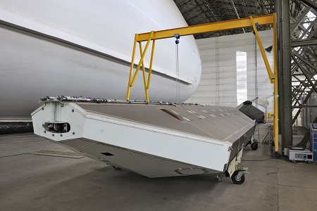
Payload and Fuel Modules
Located aft of the main mission and forward fuel modules (visible in background), the main fuel module houses up to 9 tons.
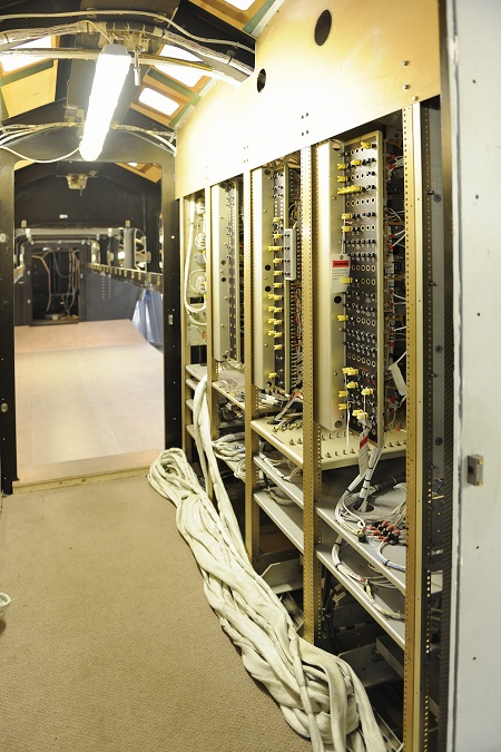
Credit: Mark Wagner, Aviation-Images.comMounted in racks aft of the cockpit and forward of the mission payload area, the electrical system handles almost one-third of a megawatt.
Credit: Mark Wagner, Aviation-Images.comSnug beneath the airship is a 149-ft.-long composite structure incorporating the flight deck, services area, payload bay and a forward fuel tank. Some 12 ft. wide for most of its length, the module narrows slightly to 10 ft. at the front where the flight deck is located. Aft of this section, connected via a 40-ft.-long centerline payload beam, is the 40-ft.-long main fuel module housing up to 9 tons of fuel. The forward tank, containing up to 4 tons and located in the aftermost part of the mission module assembly, is 60 ft. distant and produces a very long fuel movement arm. By pumping fuel between the fore and aft tanks, HAV plans to control the incidence angle for optimum long-range cruise efficiency, says Durham. Fuel travels along pipes connected to the payload beam, an aluminum honeycomb structure that can carry up to 3 tons “in the open air.”
The mission module is 69 ft. long and, empty of fuel and payload, weighs around 2.5 tons. Aft of the flight deck are racks on the port side for power distribution and, on the starboard side, mission equipment and avionics. “Each of the engines has about a 50-kw generator on it and nearly 80 kw at its peak,” says Durham. “So the electrical system has to be able to handle nearly one-third of a megawatt of electric power. It has to control it and distribute it to the mission systems, or to the fans that pump up the ballonets,” he adds. Aft of the system racks is an open area formerly occupied by the LEMV mission system. HAV is replacing the overhead supporting structure here to provide space for a 10 X 8 X 24-ft. cabin with composite frames, sidewalls and floor.
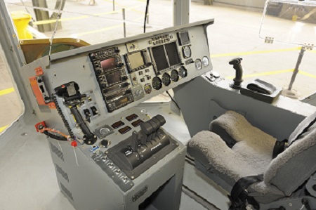
Cockpit and Flight Control System
Key features of the cockpit include the right-hand fly-by-light flight control stick and, nearer the camera, throttle and thrust vectoring controls.
Credit: Mark Wagner, Aviation-Images.comThe flight deck area is immense, with a length of 15 ft. and four floor-to-ceiling windows providing excellent visibility. Provisioned with seats for a single pilot and an observer, the cockpit was added to make the airship optionally piloted. “It was originally designed as an unmanned air vehicle, but very early in the pre-bid stages we pushed the U.S. government to adopt an optionally manned strategy because it would be easier to fly through civil controlled airspace, and we were very keen to put a pilot in the front for the transatlantic transit and down to the theater of interest,” says Durham. As a result, the current cockpit is rudimentary. “As we go forward, this will turn into a twin-pilot layout and will become more of a ‘glass’ cockpit,” he adds.
The cockpit is equipped with Garmin avionics and dominated by a GNS 430 GPS/nav/comms system, with engine status displays below it and standby instruments to the right. The suite includes a camera system that displays selectable views of the exterior and all four engines on a screen in the top center. “The pilot cannot see them any other way. You can’t even hear them from here, to a large extent,” says Durham. The camera is mounted 15 ft. ahead of each engine. An overhead panel contains controls for engines and the electrical system, while the center houses the pressure control, fuel and flight-control system.
The airship is controlled by a side stick on the right side, making it seem more familiar to rotary- than fixed-wing pilots. The stick automatically slaves to the propulsor vanes at the aft of the vehicle, “so at low speed, the pilot doesn’t have to think about the control surfaces,” says Durham. Below 30 kt., the vanes therefore work the same way as the tail fins.
On any airship, particularly a hybrid, engine control is vital to overall vehicle control. The engines are controlled by four main throttles located in a quadrant to the left. The left levers control the front engines and those on the right control the aft engines. Throttles can control forward and reverse power through actuation of the fully variable pitch control propellers on each of the engines. To the left of the throttles is a flap lever that controls the vane positions on the front engines for takeoff and landing. The lever controls three positions forward and aft, with the first detent commanding a 20-deg. up or down movement of the propulsor. The second detent adds the vane, and the third puts in 100% vane deflection.
“We spent a lot of time with pilots on the ergonomics. Originally, we had grandiose plans for a single power lever and looked at the F-35 Hotas [hand–on-throttle-and-stick], but, given the practical application of this, giving the pilot control of the four throttles is actually quite straightforward,” says Durham. There are also no rudder pedals. “One of the things is how do you do a coordinated turn? The reality is when you put it into a turn, the upper rudders cause it to roll slightly out of the turn, but as it commences the turn, the pendulum stability of the vehicle makes it roll back into a coordinated turn. So, basically, the lift center causes it to go round the corner.”
Flying surfaces and propulsors are connected to flight-control computers via a fly-by-light digital flight control network. Fiber-optic cables are preferred over the traditional electrical wiring of a fly-by-wire system because these work better over the larger scale of the vehicle and are highly resistant to electromagnetic interference and lightning strikes. Potentiometers at the pilot’s controls emit signals that are digitized and then encoded into light pulses. These are transmitted to drive units mounted next to the actuators at each control surface. “There are about 20 boxes around the vehicle that all have to talk to each other and compare notes,” says Durham. California-based Triumph Actuation Systems provides all the primary flight control actuators. “There is electrical actuation on all corners, but they are fiber-optically controlled,” he adds.
HAV is poised to start the certification effort with the European Aviation Safety Agency but says this task, as well as that of designing the flight control system, will be made easier by the natural stability of the airship. “The center of lift is all to do with the helium centroid, which is halfway up the hull. The center of weight is quite a long way below that because you have this weight in the bottom of the hull, so the vehicle naturally wants to be a pendulum and stay the right way up,” he says. “The failure modes are somewhat more benign than most aircraft. There are very few catastrophic failure modes on these sorts of aircraft, which tends to make certification a little bit easier.”
Source: Aviation Week – aviationweek.com